¶ Description hierarchy
|
|
<LandXML> | Transfer file |
||||||
|
|
<Units><Metric> | Units (Metric) | ||||||
|
|
<CoordinateSystem> | Coordinate and elevation system | ||||||
|
|
<Start> | Base point | ||||||
|
|
<Project> | Project | ||||||
|
|
<Feature> | "IM_codings" extension type coding systems |
||||||
|
|
<Application> | Application | ||||||
|
|
<Author> | Authors | ||||||
|
|
<Alignments> | Alignments (a continous alignment) | ||||||
|
|
<Alignment> | Alignment | ||||||
|
|
<CoordGeom> | Geometry | ||||||
|
|
<Line> | *1) | Line (geom. line) | |||||
|
|
<IrregularLine> | *2) | Line string | |||||
|
|
<Curve> | *1) | Circular arc (geom. line) | |||||
|
|
<Spiral> | *1) | Transition curve (geom- line) | |||||
|
|
<Profile> | Vertical profile | ||||||
|
|
<ProfAlign> | Vertical geometry | ||||||
|
|
<PVI> | *1) | Point of intersection of vertical geometry (geom. line) | |||||
|
|
<CircCurve> | *1) | Vertical circular arc (geom. line) | |||||
|
|
<CrossSects> | Cross-sections | ||||||
|
|
<CrossSect> | Cross-section | ||||||
|
|
<Feature> | "IM_crossSect" extension (stationing ref. line) cross-section parameters and superelevation |
||||||
|
|
<Feature> | "IM_coding" extension cross-section type coding |
||||||
|
|
<Feature> | "IM_coding" extension type coding alignment |
||||||
|
|
<Feature> | "IM_stringlineLayers" extension string line model |
||||||
|
|
<Feature> | "IM_stringlineLayer" extension string line model layer - alignments and name of layer |
||||||
|
|
<Feature> | "IM_coding" extension type coding |
||||||
|
|
<Feature> | "IM_plan" extension plan information |
||||||
|
|
<Roadways> | Collection of roadways | ||||||
|
|
<Roadway> | Individual roadway | ||||||
|
|
<PlanFeature> | Planimetric feature such as building footprint, guard rail, lightpole or signage | ||||||
|
|
<CoordGeom> | Plan feature geometry | ||||||
|
|
<Line> | Line (geom. line) | ||||||
|
|
<IrregularLine> | Line string | ||||||
|
|
<Curve> | Circular arc (geom. line) | ||||||
|
|
<Spiral> | Transition curve (geom-line) | ||||||
|
|
<Location> | Plan feature location | ||||||
|
|
<Feature> | plan feature details: "IM_cable" "IM_footing" "IM_railing" "IM_fence" "IM_planfeature" |
||||||
|
|
<Feature> | "IM_coding" extension type coding planfeature |
||||||
|
|
<Surfaces> | Surface group | ||||||
|
|
<Surface> | Surface | ||||||
|
|
<SourceData> | Source data | ||||||
|
|
<Breaklines> | Breaklines | ||||||
|
|
<Breakline> | Breakline | ||||||
|
<PointList3D> |
3D point list | |||||||
|
<Feature> |
"IM_coding" extension type coding breakline |
|||||||
|
|
<DataPoints> | Data points | ||||||
|
|
<PntList3D> | 3D point list | ||||||
|
|
<Feature> | "IM_coding" extension type coding data points |
||||||
|
|
<Definition> | Surface description | ||||||
|
|
<Pnts> | Vertices | ||||||
|
|
<P> | Vertex | ||||||
|
|
<Faces> | Faces | ||||||
|
|
<F> | Face | ||||||
|
|
<Feature> | "IM_structLayer" extension structural layer material properties |
||||||
|
|
<Feature> | "IM_coding" extension type coding surface |
||||||
|
|
<Feature> | "IM_plan" extension plan information |
||||||
|
|
<FeatureDictionary> | Definition dictionary of extensions | ||||||
¶ 4.1 Contents
The file describing a road or street plan contains the header informatun described in the previous section. In inframodel-compliant file transfers a road or street alignment is defined in according to the process defined in chapter 2 route planning. A LandXML file may contain plans describing several topics, i.e. the same file may contain e.g. road, street, and railway plans.
The content of the design file is defined in metric units, using an adequate number of decimals for accuracy. For example, when the length unit in use is a meter, the values must be defined to at least six decimal places. Street designs often interface with water supply and sewerage systems , which are described in the same file. The constituent surfaces of the water supply and sewerage design are defined as triangular meshes and the design information in the <PipeNetworks> element.
A road or street design in inframodel contains:
individual alignments and their purpose, defined by type coding (geometric alignments and line strings)
line string model (line string alignments)
a terrain model (the visible surface)
a structural model (the visible surface and the structural layers of the road or street)
Cross-section parameters
The plan information may optionally contain the following:
source data (random points and breaklines)
drainage plan
railway plan
waterway plan
The superelevation of the road can be described alongside the cross-section parameters. Cross-section parameters are described at the transition points, when the transition of the value of a parameter begins or ends. Superelevation encompasses the cross slope of the roadway and in case of a street also the sidewalk.
¶ 4.2 Geometry of roads and streets
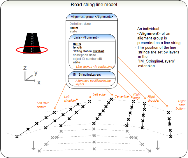
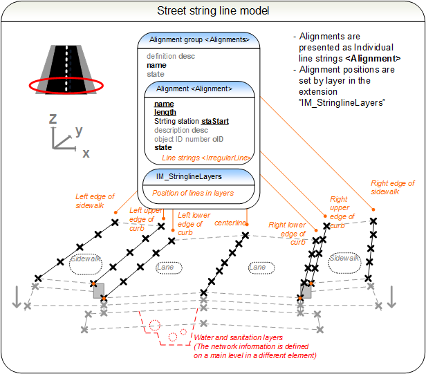
An alignment group of road or street <Alignments> contains a geometric description (description hierarchy *1) of a continuous stationing reference <Alignment>. The geometric description is composed of horizontal and vertical geometric elements. The central alignments such as the centerline and left and right edges of a road or the centerline and edges of a sidewalk for a street are described as geometric alignments while the rest are described in terms of line strings (description hierarchy *2). The alignments described as geometric descriptions are also described as line strings for use in the line string model.
The alignments <Alignment> of an alignment group <Alignments> are described before the line string model or the plan information contained by the extensions "IM_stringlinelayers" and "IM_plan". The particular order of the alignments <Alignment> within the alignment group <Alignments> does not matter. The alignment description process is described in further detain in chapter 3 Alignments.
The infraCode is set in the extension "IM_coding" - this type coding for an individual <Alignment> describes the purpose of the alignment.
Selected alignments are included in the line string model defined by the extension "IM_stringlineLayers". It is defined in the file after the <Alignment> elements and arranges line strings into surfaces using surfaceCoding.
¶ 4.3 String line model of roads and streets
Once the alignments <Alignment> of an alignment group <Alignments> are defined, the string line model of the alignment group is defined in the extension "IM_stringlineLayers". The presentation method resembles a cross-section, a layer of the string line model are referred to by their name <Alignment>.name and their location is presented as surfaces. It is not always possible to present all line strings contained by the layer in order from left to right, although this is recommended.
The detailed description of the construction process of line string model can be found in section 3.5. The string line model employs the same infraCoding system for line strings as the <Alignment>. The surface codes are set using the surfaceCoding.
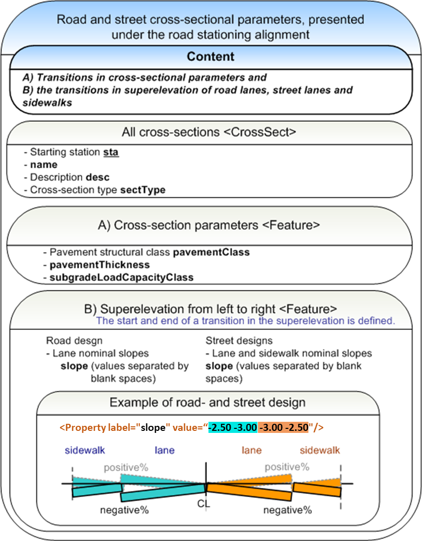
¶ 4.4 Cross-section parameters of roads and streets
The cross section parameters of an alignment group <Alignments> expand on the geometric description and line string model by defining the cross sections by station intervals in a parametric form. The cross-section parameters are set in inframodel file transfers in the "IM_crossSect" extension along with the cross-section elements. The implementation of the extension is similar to that for waterways.
The cross-section parameters describe the situation at a given station, including the cross-slopes of the roadways, streets and sidewalks. The following elaborates on the process of description: the cross-section parameters are presented at a station where a value begins or stops changing. Cross-slopes are set for each lane starting from the left to the right. A positive superelevation indicates a superelevation where the edge located further from the centerline of two is above the inner one. Accordingly, a negative one indicates that the outer edge is below the inner one.
¶ 4.4.1 Cross-section parameters
The cross-section parameters are set under <Alignment>.<CrossSects>.<CrossSect> in the extension "IM_crossSect". The cross-section parameters are optional in street designs.
It is recommended that all parameters are described along with the cross-section. When transitions from one parameter value to another occur, the start and end of the transition are defined. Details on the Finnish road design parameters are provided by Finnish Transport Infrastructure Agency (FTIA).
Attributes of <CrossSect>:
|
|
sta | alkupaalu | e.g. [0.000000] |
|
|
name | name | road: e.g. [M-2x11.75/7.5+10.00] street: e.g. [street cross-section 1] |
|
|
desc | description | road: e.g. [2 roadways] street: e.g. [2 roadways, sidewalks] |
|
|
sectType | cross-section type |
road:e.g. FTIA types a, b, c, f, x [a | b | c | f | x] type x cross-section transition begins or is in progress street: types agreed on between parties |
|
|
<CrossSects> | schema documentation | |
|
|
<CrossSect> | schema documentation |
Attributes for a single "IM_crossSect":
- pavementClass
- pavementThickness
- subgradeLoadCapacityClass
- cross slope of roads or streets
"IM_crossSect" <Feature>
|
|
name | optional name | e.g. [9] | |||
|
|
code | code | [IM_crossSect] | |||
|
|
source | source | [inframodel] | |||
| Parameters <Property> | ||||||
|
|
label | [pavementClass] | pavement class |
value | road: e.g. FTIA classes [1 | 2 | 3 | 4 | 5] | |
|
|
label | [pavementThickness] | pavement thickness | value | in file distance units e.g. [0.150000] |
|
|
|
label | [subgradeLoadCapacityClass] | subgrade load capacity class |
value | road: e.g. FTIA classes [A | B | C | D | uE | uF | uG | uH | uI] | |
|
|
label | [slope] | road: roadway or street: roadway and sidewalk cross-slopes |
value | %, left to right, space as value separator road: e.g. [-2.00 -2.00] street: e.g. [-2.50 -3.00 -3.00 -2.50] |
|
|
|
<Feature> | schema documentation | |
|
|
<Feature> | road plan short example | |
|
|
<Feature> | street plan short example |
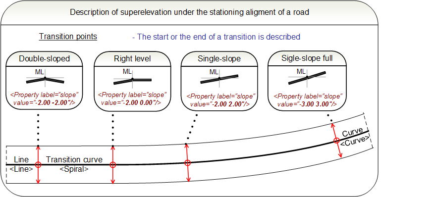
¶ 4.4.2 Transitions in superelevation
The superelevation is defined at the transition points, when a transition in the superelevation either begins or end. The cross-slopes are defined along with the cross-section parameters. The following picture illustarates the process in a road design environment.
|
|
<Feature> | schema documentation | |
|
|
<Feature> | road plan short example | |
|
|
<Feature> | street plan short example |
¶ 4.5 Terrain model and structural model of road or street
The process of constructing a terrain model or structural model is described in detail in the sections 3.6 Terrain model and 3.7 Structural model of a route. The terrain model only contains a triangle mesh of the visible surfaces. The structural model contains all the structure boundaries. All layers in the terrain model and the structural model may be assigned a type code (surfaceCoding).
It is also possible to attach source data point or breakline information to the meshes, with assigned a type code (terrainCoding). The process is described in further detail in the section 2.3 Source data.
The example illustrations below demonstrate the composition of structural models in road and street design.
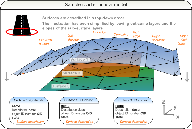
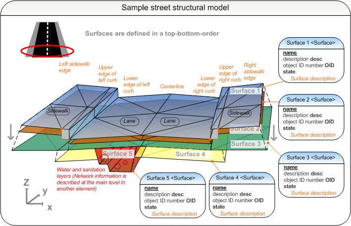
¶ 4.5.1 Structural layers
The material properties of a structural layer between two surfaces are assigned to its top surface, i.e. in a structural model of road or street an "IM_structLayer" <Feature> extension describes the soil properties below the <Surface>.
Details of <Surface> in "IM_structLayer" <Feature>
|
|
name | optional name | e.g. [9] | |||
|
|
code | code | [IM_structLayer] | |||
|
|
source | source | [inframodel] | |||
| Parameters <Property> | ||||||
|
|
label | [material] | material name of the structural layer according to applicable guideline, e.g: - Asfalttinormit 2011 (PANK Ry. 2011) - Tierakenteen suunnittelu (Tiehallinto 2005) - Tietoa tiensuunnitteluun 71D (Tiehallinto 2005) - Päällysrakenteen stabilointi (Tiehallinto 2007) - Kevennysrakenteiden suunnittelu (Liikennevirasto 2011) |
value | e.g. [KaM] | |
|
|
label | [grainSizeMin] | minimum grain size of the material in diameter units | value | e.g. [0] | |
|
|
label | [grainSizeMax] | maxmum grain size of the material in diameter units | value | e.g. [0.06] | |
|
|
label | [nominalThickness] | nominal thickness of the product in height units | value | e.g. [0.8] | |
|
|
label | [strength] | material strength (MPa) | value | e.g. [10] | |
|
|
label | [E-module] | E-module used in dimensioning road structure (MPa) | value | e.g. [10] | |
|
|
label | [loadCapacity] | load-bearing capacity or the structure (MPa) | value | e.g. [10] | |
¶ 4.6 Road plan features
The road planimetric features such as fences, guard rails, lightpole or signage footings that are assigned to a particular road or street are described under roadways. A roadways collection <Roadways> may consist of several roadway <Roadway> elements. Each roadway has a reference to its stationing reference line <Alignment>, and it can hold a number of <PlanFeatures>.
Attributes of the roadways collection <Roadways> are not used in inframodel.
Attributes of a roadway <Roadway>:
|
|
name | unique name | e.g. [E18] Note: this shall match the Alignments@name of the alignment group where the alignment referenced by alignmentRefs is found |
|
|
alignmentRefs | reference to Alignment@name | e.g. [stationing reference line] |
|
|
desc | description | e.g. [Route E18 road signage footing plans] |
|
|
state | state | [abandoned] [destroyed] [existing] [proposed] |
¶ 4.6.1 Plan features
The individual plan features are each described under <PlanFeature>, having a mandatory and unique name and optionally <Location> and geometry as <CoordGeom>.
Attributes of <PlanFeature>:
|
|
desc | description | e.g. [Steel mesh fence] |
|
|
name | unique name | e.g. [f_123] |
|
|
state | state |
[abandoned] [destroyed] [existing] [proposed] |
<PlanFeature> geometry is described in <CoordGeom> using line strings for linear features, e.g. cables, railings and fences. For point features, such as footings, location is given in <Location> element as a two or three dimensional point:
<Location>northing easting (elevation)<Location>
Details of <PlanFeature> are described as <Feature> extension, defined for each type as follows:
1. Cable information in "IM_cable" extension
2. Footing information in "IM_footing" extension
3. Railing information in "IM_railing" extension
4. Fence information in "IM_fence" extension
5. Surface structure properties in "IM_surfaceStructure" extension
6. Generic plan feature in "IM_planfeature" extension
Additionally, all plan features may be type coded in <Feature> using 7. Type coding in "IM_coding" extension.