¶ Description hierarchy
|
|
<LandXML> | Transfer file | ||||||
|
|
<Units><Metric> | Units (metric) | ||||||
|
|
<CoordinateSystem> | Coordinate and elevation system | ||||||
|
|
<Start> | Base point | ||||||
|
|
<Project> | Project | ||||||
|
|
<Feature> | "IM_codings" extension type coding systems |
||||||
|
|
<Application> | Application | ||||||
|
|
<Author> | Authors | ||||||
|
|
<Alignments> | Alignment group (with one continuous stationing alignment) | ||||||
|
|
<Alignment> | Alignment | ||||||
|
|
<CoordGeom> | Geometry (according to the described item) | ||||||
|
|
<Line> | *1) | Line (geometry alignment) | |||||
|
|
<IrregularLine> | *2) | Line string | |||||
|
|
<Curve> | *1) | Circular arc (geometry alignment) | |||||
|
|
<Spiral> | *1) | Transition curve (geometry alignment) | |||||
|
|
<Profile> | Vertical profile (according to the described item) | ||||||
|
|
<ProfAlign> | Vertical geometry | ||||||
|
|
<PVI> | *1) | Point of Vertical Intersection (geometry alignment) | |||||
|
|
<CircCurve> | *1) | Vertical circular arc (geometry alignment) | |||||
|
|
<CrossSects> | Cross-sections | ||||||
|
|
<CrossSect> | Cross-section | ||||||
|
|
<Feature> | "IM_crossSect" extension (stationing ref. line) Cross-section parameters |
||||||
|
|
<Feature> | "IM_coding" extension type coding Alignment |
||||||
|
|
<Feature> | "IM_stringlineLayers" extension line string model |
||||||
|
|
<Feature> | "IM_stringlineLayer" extension line string model layer - name and alignments in layer |
||||||
|
|
<Feature> | "IM_coding" extension type coding |
||||||
|
|
<Feature> | "IM_plan" extension plan information |
||||||
|
|
<Roadways> | Collection of waterways | ||||||
|
|
<Roadway> | Individual waterway | ||||||
|
|
<PlanFeature> | Planimetric feature such as building footprint, guard rail, lightpole or signage | ||||||
|
|
<CoordGeom> | Plan feature geometry | ||||||
|
|
<Line> | Line (geom. line) | ||||||
|
|
<IrregularLine> | Line string | ||||||
|
|
<Curve> | Circular arc (geom. line) | ||||||
|
|
<Spiral> | Transition curve (geom-line) | ||||||
|
|
<Location> | Plan feature location | ||||||
|
|
<Feature> | plan feature details: "IM_cable" "IM_footing" "IM_railing" "IM_fence" "IM_planfeature" |
||||||
|
|
<Feature> | "IM_coding" extension type coding planfeature |
||||||
|
|
<Surfaces> | Surface group | ||||||
|
|
<Surface> | Surface | ||||||
|
|
<SourceData> | Source data | ||||||
|
|
<Breaklines> | Breaklines | ||||||
|
|
<Breakline> | Breakline | ||||||
|
<PointList3D> |
3D point list | |||||||
|
<Feature> |
"IM_coding" extension type coding Breakline |
|||||||
|
|
<DataPoints> | Random points | ||||||
|
|
<PntList3D> | 3D point list | ||||||
|
|
<Feature> | "IM_coding" extension type coding Random points |
||||||
|
|
<Definition> | Surface definition | ||||||
|
|
<Pnts> | Vertices | ||||||
|
|
<P> | Vertex | ||||||
|
|
<Faces> | Triangle mesh | ||||||
|
|
<F> | Face | ||||||
|
|
<Feature> | "IM_coding" extension type coding Surface |
||||||
|
|
<Feature> | "IM_plan" extension plan information |
||||||
|
|
<FeatureDictionary> | extension definitions | ||||||
¶ 6.1 Content
An inframodel compliant file transfer utilizes the header information defined in chapter 1 Headers. The plan is described as appropriate according to the guidelines laid out in chapter 3 Route planning (general). All plan information contained in the file utilize a common coordinate, elevation and unit system. The utilized units are metric units appropriate for the file content.
The geometry of a waterway is not described by tangent points in this context. An waterway design contains at least one alignment group <Alignments> composed of alignments <Alignment>, a string line model or a surface model and a structural model. Surfaces can have source data point or breakline information attached to them. In addition, the cross-section, minimum depth, minimum width and dimensioning water level height is described.
¶ 6.2 Waterway geometry
Inframodel waterways <Alignments> must have a continuous stationing reference alignment. This alignment and other central alignments are presented as geometric alignments (description hierarchy *1).In waterway designs, the stationing reference line and the left and right edge alignments are usually described as geometric alignments. A geometric alignment contains information about the horizontal and vertical dimensioning elements of an alignment. Other alignments are described in terms of line strings (description hierarchy *2). The geometric alignments are also given a line string representation for use in the line string model. The process is described in further detail in chapter 3 Route planning (general).
The alignment group must contain at least one continuous geometric alignment as the stationing reference line. The reference line may be something other than the alignment centerline and its position relative to the centerline may vary. The tangent points are not described in the alignment definition. They can, however, be described as separate line strings <Alignment>. The elevation of the centerline is usually set to the average lowest height of the sailing season in inland bodies of water.
The order the individual <Alignment> elements are described in under the <Alignments> element does not matter. The type coding of individual alignments defines the purpose of the alignment. A terrainCoding-compliant terrain code is set in the extension "IM_coding". Selected alignments are included in the line string model, defined in the extension "IM_stringLineLayers". The line string model consists of alignments structured into surfaces using a surfaceCoding. The surface model and structural model of the design are defined as triangle meshes. The plan information is optionally set in the "IM_plan" extension.
¶ 6.3 Cross section parameters
The cross-section parameters of an alignment group describe the values of cross-sectional parameters from a the given station onwards. The cross-section parameters are set in the extension "IM_crossSect". The extension is implemented in a fashion similar to road and street design. The parameters are minimum depth of the route, the minimum width and the dimensioning waterLevel. The dimensioning water level is situation-specific and might be e.g. average daily low or average daily mean water level. The described Cross-section parameters are valid from the set station onwards.
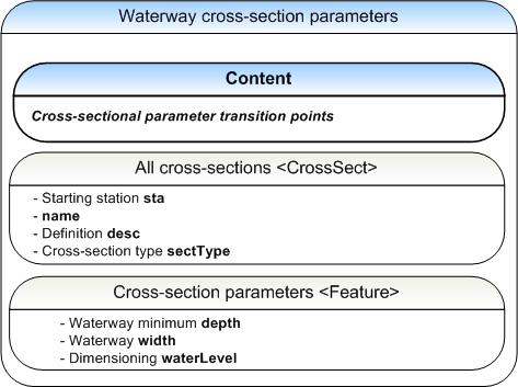
The cross-section parameters are set for the stationing reference alignment cross-sections <Alignment>.<CrossSects>.<CrossSect> in the "IM_crossSects" extension <Feature>. The first cross-section of the alignment is defined by describing all parameters of the cross-section. The parameters of the following cross-sections are only described if a value begins or stops changing.
Cross section <CrossSect> attributes
|
|
sta | starting station |
e.g. [0.000000] |
|
|
name | name | Agreed on by the parties, e.g. [Cross-section1] |
|
|
desc | description | e.g. [stations 0.00 - 1150.31] |
|
|
sectType | Cross-section type |
Agreed on by the parties, e.g. [non-symmetric] |
|
|
<CrossSects> | schema documentation | |
|
|
<CrossSect> | schema documentation |
attributes of the extension "IM_crossSect":
- minimum depth
- minimum width
- dimensioning waterLevel
"IM_crossSect" <Feature>
|
|
name | unique name | e.g. [11] | |||
|
|
code | code |
[IM_crossSect] | |||
|
|
source | source |
[inframodel] | |||
| Parameters <Property> | ||||||
|
|
label | [depth] | minimum depth of the waterway |
value | in file distance units, e.g. [4.500000] | |
|
|
label | [width] | minimum width of the waterway | value | in file distance units, e.g. [15.000000] | |
|
|
label | [waterLevel] | dimensioning water level |
value | in file distance units, absolute height in chosen elevation system e.g. [0.200000] | |
|
|
<Feature> | schema documentation | |
|
|
<Feature> | short example |
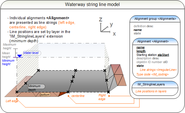
¶ 6.4 String line model
The string line model of an alignment group <Alignments> is defined in the extension "IM_stringlineLayers" after the alignments <Alignment>. A line string layer is presented by refering to the names of its constituent alignments <Alignment>.name.
The line string model of routes is described in further detail in section 3.5. The constituent line strings <Alignment> of the string line model adhere to the terrain codes (terrainCoding) defined for the line strings. The layers of the line string model are defined by assigning them a surface code.
|
|
stringline model short example |
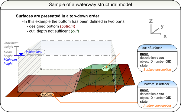
¶ 6.5 Surface and structural model
The structural model of a waterway is described in detail in section 3.7 Structural model. The surface model contains at least one triangular mesh that describes the bottom of the waterway. The structural model contain at least the water level in addition to this. It is possible to define surface codes (surfaceCoding) for all surfaces.
It is possible to attach source data point and breakline information to surfaces. The process is described in further detail in section 2.2.
¶ 6.6 Waterway plan features
The waterway planimetric features such as guard rails, lightpole or signage footings that are assigned to a particular waterway are described under roadways. A roadways collection <Roadways> may consist of several roadway <Roadway> elements. Each roadway has a reference to its stationing reference line <Alignment>, and it can hold a number of <PlanFeatures>.
Attributes of the roadways collection <Roadways> are not used in inframodel.
Attributes of a roadway <Roadway>:
|
|
name | unique name | e.g. [W001] Note: this shall match the Alignments@name of the alignment group where the alignment referenced by alignmentRefs is found |
|
|
alignmentRefs | reference to Alignment@name | e.g. [001] |
|
|
desc | description | e.g. [Route W001 signage footing plans] |
|
|
state | state | [abandoned] [destroyed] [existing] [proposed] |
¶ 6.6.1 Plan features
The individual plan features are each described under <PlanFeature>, having a mandatory and unique name and optionally <Location> and geometry as <CoordGeom>.
Attributes of <PlanFeature>:
|
|
desc | description | e.g. [Steel mesh fence] |
|
|
name | unique name | e.g. [f_123] |
|
|
state | state |
[abandoned] [destroyed] [existing] [proposed] |
<PlanFeature> geometry is described in <CoordGeom> using line strings for linear features, e.g. cables, railings and fences. For point features, such as footings, location is given in <Location> element as a two or three dimensional point:
<Location>northing easting (elevation)<Location>
Details of <PlanFeature> are described as <Feature> extension, defined for each type as follows:
1. Cable information in "IM_cable" extension
2. Footing information in "IM_footing" extension
3. Railing information in "IM_railing" extension
4. Fence information in "IM_fence" extension
5. Surface structure properties in "IM_surfaceStructure" extension
6. Generic plan feature in "IM_planfeature" extension
Additionally, all plan features may be type coded in <Feature> using 7. Type coding in "IM_coding" extension.